Hello,
There are two small wires, one white and one black. I am unsure which color to solder at what points onto the coaxial part. There are two pegs on the coaxial. One protruding out of the back end of the coaxial, and one on the side.
If you have this option, please let me know. I don't want to swap these around and damage something. Thanks.
Installing the DI-TRI, what to solder PLEASE HELP!!!!
Moderators: Sharp, X-Trade, Pepperpotty, karmathanever
Installing the DI-TRI, what to solder PLEASE HELP!!!!
Last edited by Bach42t on Mon Oct 11, 2010 1:14 am, edited 2 times in total.
-
Trinity2112

- Platinum Member
- Posts: 578
- Joined: Wed Feb 20, 2002 5:35 pm
- Location: Delaware, USA
I googled for an image of the DI-TRI and this is the largest one I could find...which is no help. It's the one on the far left:

Current Korg Lineup: Kronos 61, Oasys 76 · M3-61/RADIAS · Trinity Plus/HDR · 01/WFD · 01R/W · X3R · M3R · Wavestation EX · Wavestation SR · Triton Rack/MOSS · Z1EX · TR-Rack · Karma · D3200 · iM1 · iWavestation · iMono/Poly
Other Synths: Berhinger Deepmind 12 · iProphet · Moog Model D
Dearly departed: X3
Other Synths: Berhinger Deepmind 12 · iProphet · Moog Model D
Dearly departed: X3
Oh crap. Looks like I am missing something. I don't have that black piece that surrounds the BNC adapter. I think that's just a shield of some sort. I believe I could still use it though. I will have to attach and solder the wires on.Trinity2112 wrote:I googled for an image of the DI-TRI and this is the largest one I could find...which is no help. It's the one on the far left:
I hope this thing ends up working in the end.
-
Trinity2112
- Platinum Member
- Posts: 578
- Joined: Wed Feb 20, 2002 5:35 pm
- Location: Delaware, USA
I think it acts only as a housing for the adapter. Can you tell if the adapter sits in a certain position? If so, I think the peg facing up would receive the white wire.....judging by the two photos I've seen.
Current Korg Lineup: Kronos 61, Oasys 76 · M3-61/RADIAS · Trinity Plus/HDR · 01/WFD · 01R/W · X3R · M3R · Wavestation EX · Wavestation SR · Triton Rack/MOSS · Z1EX · TR-Rack · Karma · D3200 · iM1 · iWavestation · iMono/Poly
Other Synths: Berhinger Deepmind 12 · iProphet · Moog Model D
Dearly departed: X3
Other Synths: Berhinger Deepmind 12 · iProphet · Moog Model D
Dearly departed: X3
-
pegnafroy
- Full Member
- Posts: 201
- Joined: Thu Apr 19, 2007 3:44 am
- Location: Penaflor, Santiago of Chile
Hi:
User Salcerin gave me some pics of the board uninstalled. But, sorry, i lost them.
I can help anyway.
Let's begin:
- First, you need to buy a new BNC connector, we need to start with all the pieces together. They are so cheap.
- Then, save your data and sounds on a pair of diskettes, or make a midi dump to trinitro.
- Power off your keyboard and disconnect it.
- Turn face down your keyboard on a table and make sure that the joystick is out of the table (ouch!!).
- Open the board.
- Loose the Motherboard. And only disconnect the cables that not let you move the board a little (solo-tri and scsi/hdr-tri).
- Take out the plate that cover the holes of the bnc and the light pipe conectors. With care but firmly, they are glued to the chasis. Of course, take out the screws first.
- install the bnc conector from the outside (that's why you need to solder after the bnc is installed). You will see that the BNC conector can't pass all the way into the hole.
- Take the ground conector ring (it has a solder tip, for the ground cable) and pass it over the bnc conector from the INSIDE.
- Take the nut that secure the BNC and tight it from the inside.
- Now, it's time to look the white conector and the di-tri board itself.
- Connect the white conector into the di-tri board. Look that since can be installed in both ways, it can be installed correctly just in one way. So you need to look carefully your connector.
- Now turn down the board (remember that we have not installed the board into the MOBO yet) and look the draws. Search the 3 pins that are just below the white connector. Then look the pin that is connected to the ground of the board (is the only one that is connected to to most of the drawing) then mark it with a "-".
- Turn up the di-tri and search for the same pin, and mark the connector or the pin, or whatever help you to recognize the ground pin. Look the cable, which color is it??? then take that cable and solder the other end to the ground pin on the bnc cable. Of course, disconnect the white connector first.
- Take the other cable and solder it to the central pin on the BNC connector.
- Connect again the white connector into the properly socket on the di-tri.
- Now we can install the di-tri on the motherboard. Secure it with 2 screws.
- Now secure the Motherboard again.
- Connect again the cables that you disconnect early.
- Close the trinity.
- Turn up the keyboard.
- Connect it to the power inlet and power it with "0" and "enter" buttons pressed.
- If all works properly you will see the trinity logo came up with the words "WITH DI-TRI" on it.
I can't saw the images posted early, and i posted that guide without my keyboard in front of me. So if the descriptions are not accurate, i'm sorry. But take my words in order that you learn how to install the di-tri and correct the wrong indications, since the direction is right.
Take pics on every stage, so it will be easy to put all together again.
Hope it helps.
F.
OK, I got a little lost at this point in your instructions. They are helping me out, but I am a little confused:
And with the white cable I solder it to the center post of the BNC, then I attach the DI-TRI to the MOBO and continue on with the rest of your instructions.
Does this sound correct???
Also, today I am on the lookout at electronics supply for the BNC connector. Having difficulty finding one locally. Hopefully, so I can do this install tonight.
What I have (as you can see in the picture) is the white plug (which attaches to the DI-TRI) with black and white wire coming out of it. I was under the belief that I take the black wire and solder it to the ground connector ring.pegnafroy wrote:
- Now turn down the board (remember that we have not installed the board into the MOBO yet) and look the draws. Search the 3 pins that are just below the white connector. Then look the pin that is connected to the ground of the board (is the only one that is connected to to most of the drawing) then mark it with a "-".
- Turn up the di-tri and search for the same pin, and mark the connector or the pin, or whatever help you to recognize the ground pin. Look the cable, which color is it??? then take that cable and solder the other end to the ground pin on the bnc cable. Of course, disconnect the white connector first.
- Take the other cable and solder it to the central pin on the BNC connector.
- Connect again the white connector into the properly socket on the di-tri.
And with the white cable I solder it to the center post of the BNC, then I attach the DI-TRI to the MOBO and continue on with the rest of your instructions.
Does this sound correct???
Also, today I am on the lookout at electronics supply for the BNC connector. Having difficulty finding one locally. Hopefully, so I can do this install tonight.
-
pegnafroy
- Full Member
- Posts: 201
- Joined: Thu Apr 19, 2007 3:44 am
- Location: Penaflor, Santiago of Chile
Here in my work i can't see the pics, and my trustie trinity is at my parents house. Anyway, i can assure that if you follow the logic of my guide, you will install the board quickly. Remember, the most important part is to recognize the "-" wire. The other instructions are mostly accurate.Bach42t wrote:What I have (as you can see in the picture)
Good luck.
F.
Could you get to a computer where you can look at the picture? I want to make sure I understand. I am trying to understand through your grammar, and I think I do... I just need to make sure what you are talking about and you can confirm with picture.pegnafroy wrote:Remember, the most important part is to recognize the "-" wire. The other instructions are mostly accurate.Bach42t wrote:What I have (as you can see in the picture)
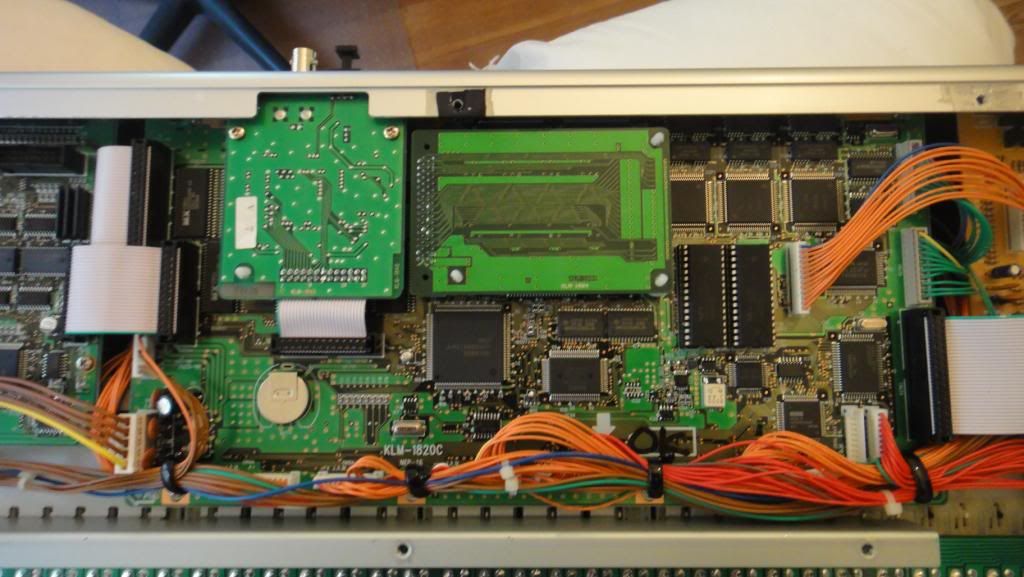
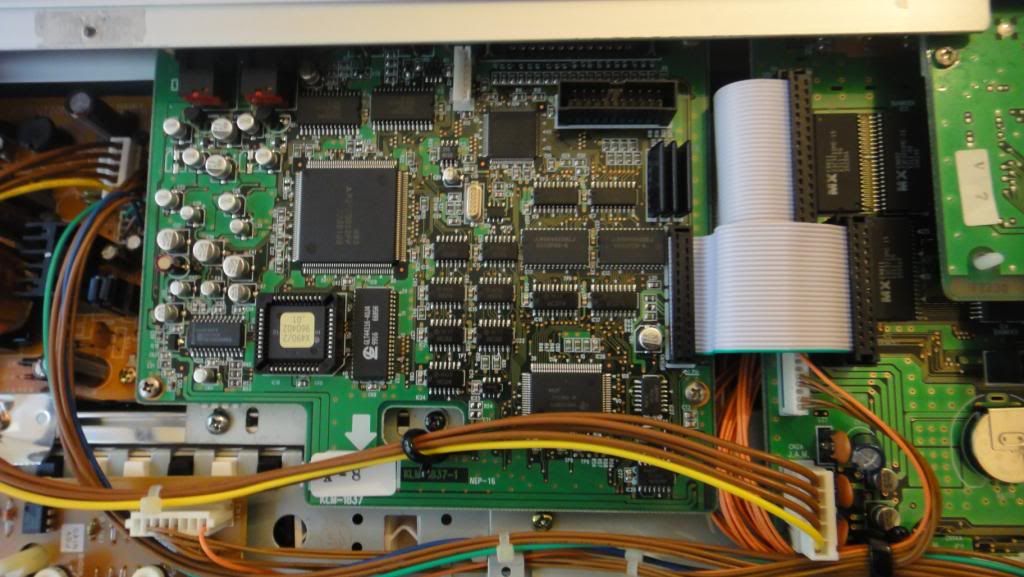
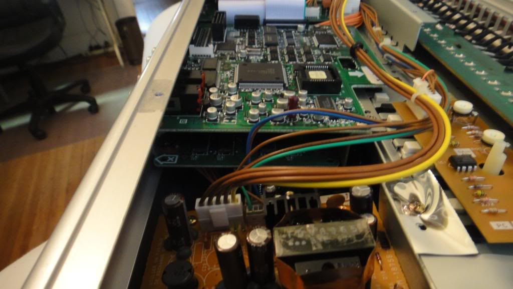
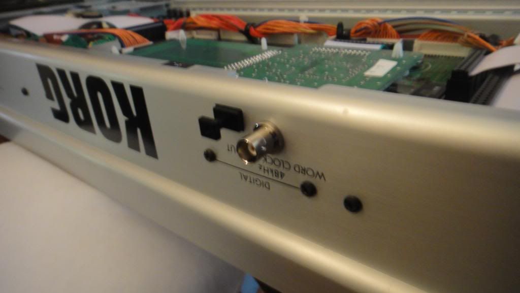
Pics after install.....
<a href="http://s73.photobucket.com/albums/i231/ ... C00078.jpg" target="_blank"><img src="http://i73.photobucket.com/albums/i231/ ... C00078.jpg" border="0" alt="Photobucket"></a>
<a href="http://s73.photobucket.com/albums/i231/ ... C00079.jpg" target="_blank"><img src="http://i73.photobucket.com/albums/i231/ ... C00079.jpg" border="0" alt="Photobucket"></a>
<a href="http://s73.photobucket.com/albums/i231/ ... C00080.jpg" target="_blank"><img src="http://i73.photobucket.com/albums/i231/ ... C00080.jpg" border="0" alt="Photobucket"></a>
<a href="http://s73.photobucket.com/albums/i231/ ... C00081.jpg" target="_blank"><img src="http://i73.photobucket.com/albums/i231/ ... C00081.jpg" border="0" alt="Photobucket"></a>
<a href="http://s73.photobucket.com/albums/i231/ ... C00083.jpg" target="_blank"><img src="http://i73.photobucket.com/albums/i231/ ... C00083.jpg" border="0" alt="Photobucket"></a>